FACADE
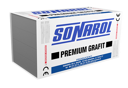
EPS S 031 premium grafit
A product for thermal insulation layers with a very high thermal insulating power (thanks to a graphite composition) on areas with a minimum exposure to loads:
- Thermal insulation of walls with cladding and ventilated air gaps
- Thermal insulation of cornice pieces, integrated as sacrificial formwork under plaster
- Thermal insulation of outer walls in EIFS barrier systems (with insulated render)
- Thermal insulation of window lintels
- Thermal insulation of balcony loggias
- Thermal insulation of timber frame floors
- Thermal insulation of framed walls
- Other applications compatible with the product’s declared parameters.

0,031 [K/mW]
Declared heat transfer coefficient

| Thickness dN [mm] | 20 | 30 | 40 | 50 | 60 | 70 | 80 | 90 | 100 | 110 | 120 | 130 | 140 | 150 | 160 |
|---|---|---|---|---|---|---|---|---|---|---|---|---|---|---|---|
| Heat resistance RD [m2 K/W] | 0,60 | 0,90 | 1,20 | 1,55 | 1,85 | 2,15 | 2,45 | 2,75 | 3,10 | 3,40 | 3,70 | 4,00 | 4,30 | 4,65 | 4,95 |
| Thickness dN [mm] | 170 | 180 | 190 | 200 | 210 | 220 | 230 | 240 | 250 | 260 | 270 | 280 | 290 | 300 | |
|---|---|---|---|---|---|---|---|---|---|---|---|---|---|---|---|
| Heat resistance RD [m2 K/W] | 5,25 | 5,55 | 5,85 | 6,20 | 6,50 | 6,80 | 7,10 | 7,40 | 7,75 | 8,05 | 8,35 | 8,65 | 8,95 | 9,30 |
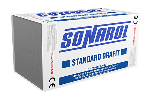
EPS S 033 standard grafit
A product for thermal insulation layers with a very high thermal insulating power (thanks to a graphite composition) on areas with a minimum exposure to loads:
- Thermal insulation of walls with cladding and ventilated air gaps
- Thermal insulation of outer walls integrated with EIFS barrier systems (with insulated render)
- Thermal insulation of cornice pieces, integrated as sacrificial formwork under plaster
- Thermal insulation of opening lintels and frames
- Thermal insulation underneath floors concealed under cladding
- Thermal insulation underneath floors in EIFS barrier systems
- Thermal insulation of sloping roofs, installed in between the rafters
- Other applications compatible with the product’s declared parameters.

0,033 [K/mW]
Declared heat transfer coefficient

| Thickness dN [mm] | 20 | 30 | 40 | 50 | 60 | 70 | 80 | 90 | 100 | 110 | 120 | 130 | 140 | 150 | 160 |
|---|---|---|---|---|---|---|---|---|---|---|---|---|---|---|---|
| Heat resistance RD [m2 K/W] | 0,55 | 0,85 | 1,15 | 1,45 | 1,70 | 2,00 | 2,30 | 2,60 | 2,90 | 3,15 | 3,45 | 3,75 | 4,05 | 4,35 | 4,60 |
| Thickness dN [mm] | 170 | 180 | 190 | 200 | 210 | 220 | 230 | 240 | 250 | 260 | 270 | 280 | 290 | 300 | |
|---|---|---|---|---|---|---|---|---|---|---|---|---|---|---|---|
| Heat resistance RD [m2 K/W] | 4,90 | 5,20 | 5,50 | 5,80 | 6,05 | 6,35 | 6,65 | 6,95 | 7,25 | 7,50 | 7,80 | 8,10 | 8,40 | 8,70 |

DESIGN CALCULATOR
Calculate


 Back
Back